PROJECT PORTFOLIO
Architectural Structure Design
Our architectural structural design services ensure safety, durability, and functionality through comprehensive structural planning, stress analysis, and cross-sectional design. We develop resilient structures capable of withstanding external forces such as earthquakes, wind, and snow loads—creating safe and comfortable architectural spaces. Our team proposes optimal structural systems— including steel-frame structures, reinforced concrete (RC) structures, and hybrid systems— tailored to each building’s purpose, requirements, scale, and conditions. By seamlessly integrating structural design with architectural aesthetics and facility requirements, we contribute to the realization of safe, sustainable, and high-quality buildings.
Ice Arena
- Project Location
- Niigata Prefecture, JAPAN
- Applicable Standards
- Building Standards Act
- Building Scale
- Floor area: 66.8m × 78.3m, Height: 14.6m, Two stories above ground.
- Intended Use
- Ice Arena
- Design Load
- The distribution of external forces during an earthquake was calculated using Ai distribution in accordance with the Building Standards Act.
As this is a region with heavy snowfall, snow loads were also considered as long-term loads. - Structural System
- XY Direction: Combined moment resisting frame with braced frame structure with dampers
Roof: Three-dimensional truss structure using steel pipes - Software & Tools
- Union System / Super Build SS3, MIDAS IT /MIDAS iGen
Key Design Considerations
• The arena features a large column-free space, with a main rink of 28.8m × 64.8m and a sub rink of 17.8m × 45.0m. To achieve this, a three-dimensional steel pipe truss system was adopted for the roof structure.• Due to its location in a heavy snow region, the roof was designed to withstand up to 1.0m of snow accumulation, considering both short-term and long-term snow loads.
• The main supporting columns for the roof truss are reinforced concrete (RC) cylinders, designed to withstand significant vertical loads. Inclined steel columns are placed atop these RC columns to effectively reduce the roof truss span.
• The long-span roof trusses are designed to accommodate both snow loads and vertical seismic forces.
• To mitigate seismic vibrations in the expansive column-free layout, dampers are installed along the building perimeter.
• Solar panels are installed on the roof to support energy sustainability.
• At the front of the building, the three-dimensional roof truss curves down to ground level and connects to the foundation using roller bearing supports, which help reduce stress concentration at the connection point.
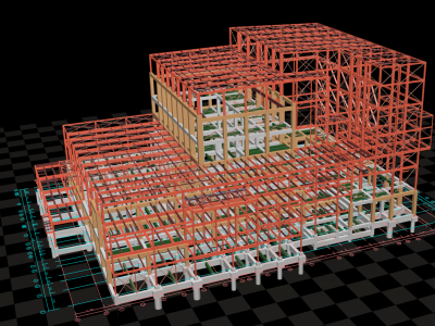
Design of Waste Treatment Facilities
- Project Location
- Tokyo, JAPAN
- Applicable Standards
- Building Standards Act
- Building Scale
- Floor area: 60.0m × 80.5m, Height: 38.7m, Six stories above ground, Two stories below ground.
- Intended Use
- Waste treatment facility
- Design Load
- The distribution of external forces during earthquakes was calculated based on the Ai distribution as per the Building Standards Act.
Snow loads were calculated using an increased coefficient to account for the low-slope roof.
- Structural System
- XY direction: Frame structure with seismic walls (SRC + RC construction), Frame structure with bracing (S construction).
- Software & Tools
- Union System / Super Build SS3, MIDAS IT / MIDAS iGen
Key Design Considerations
• Structural types were chosen based on the specific role and load conditions of each area.○ Reinforced Concrete (RC) structures were mainly used directly under major plant equipment. This choice was made to ensure sufficient stiffness and strength, which are essential for supporting heavy loads from the equipment.
○ Steel (S) structures were used for the surrounding framework, such as walls and roofs. Steel was selected for these parts to reduce overall structural weight without compromising performance.
○ Steel Reinforced Concrete (SRC) structures were adopted in critical areas like the waste pit and crane zones, where repeated loading (e.g., from crane operations) occurs. SRC offers high stiffness and strength, making it more suitable for withstanding long-term cyclic stresses in these zones.
• Full slits were introduced at hanging wall and spandrel wall around beam-column joints where wall openings (windows, doors, utility ducts) could cause early shear failure.
• Due to sloped supporting ground, a hybrid foundation system is used, combining spread foundations and cast-in-place concrete pile foundations. To prevent differential settlement, vertical spring elements are considered in the foundation model.
• Due to sloped supporting ground, a combination of shallow and pile foundations (cast-in-place concrete piles) was used. To prevent differential settlement, vertical spring elements were considered in the foundation model.
• For waste pits, which are subjected to significant lateral pressure, a finite element method (FEM) analysis was performed. The structure was modeled using 0.50 m grid plate elements to account for differences in rigidity between the bottom slab and surrounding walls, and the results confirmed structural safety.
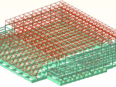
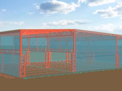
Overhead Crane Support Building
- Project Location
- Aichi Prefecture, JAPAN
- Applicable Standards
- Building Standards Act
- Building Scale
- Floor area: 75.0m × 100.65m, Height: 23.3m.
- Intended Use
- Facility structure for manufacturing lanes within a steel mill
- Design Load
- The distribution of external forces during earthquakes was calculated based on the Ai distribution as per the Building Standards Act.
Snow loads were calculated using an increased coeƯicient to account for the low-slope roof. - Structural System
- Steel frame construction
• Short-span direction: Braced structure (truss system)
• Long-span direction: Moment-resisting frame (with lattice columns) - Software & Tools
- Union System / Super Build / SS7
Key Design Considerations
• The structure adopts steel frame construction, primarily using H-shaped steel for columns and beams. Partial truss structures were also incorporated in select beam and column locations.• Structural analysis was performed under Design Route 3 guidelines.
• The building is officially classified as a single-story structure for permit purposes, but for structural design, it was treated as a two-story structure to ensure adequate strength and stability.
• With column spans reaching approximately 32 meters, truss beams and H-section steel beams with a depth of 1200 mm were used to ensure resistance to roof loads and snow loads.
• The building is designed to support three overhead cranes (each with a capacity of 30–40 tons) and one suspension crane (10 tons). Structural analysis was performed for approximately 16 different loading scenarios, considering various crane positions and both fully and partially loaded conditions.
• To resist the large shear forces generated at the column bases—particularly from seismic and crane loads-shear keys were installed beneath the base plates to enhance horizontal load resistance.
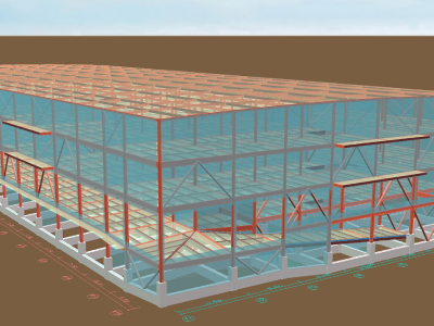
Logistics Warehouse
- Project Location
- Saitama Prefecture, JAPAN
- Applicable Standards
- Building Standards Act
- Building Scale
- Floor area: 180.8m × 76.0m, Height: 28.2m, Four stories above ground.
- Intended Use
- Logistics warehouse
- Design Load
- The distribution of external forces during earthquakes was calculated based on the Ai distribution as per the Building Standards Act.
Snow loads were calculated using an increased coefficient to account for the low-slope roof. - Structural System
- XY Direction: Combined moment resisting frame with braced frame structure
- Software & Tools
- Union System / Super Build/SS7 / MIDAS IT / MIDAS iGen
Key Design Considerations
• The structural system adopts steel frame construction, with square steel pipes or H-shaped steel for columns, and H-shaped steel for beams. Buckling-restrained braces (BRBs) and channel steel brace provide seismic resistance.• Structural analysis was performed under Design Route 3 guidelines.
• The first and second floors are designed to allow trucks to enter for loading and unloading, with a ramp connecting to the second floor inside the building.
• Designed for heavy-duty usage, the structural system accommodates floor loads of 1.5 to 2.0 tons/m², typical for a logistics warehouse.
• The column bases are designed as embedded bases (root-wrapped columns).
• The foundation employs a pile foundation system using pre-boring methods with SC piles and PHC piles. To anchor pile heads, the F .T PILE method was used, effectively reducing bending stress in both the piles and building's underground beams.
• Given the building’s long span (approx. 180 meters), thermal stress analysis was separately performed to account for thermal expansion of the steel frame. Results confirmed that thermal stresses are within acceptable limits.
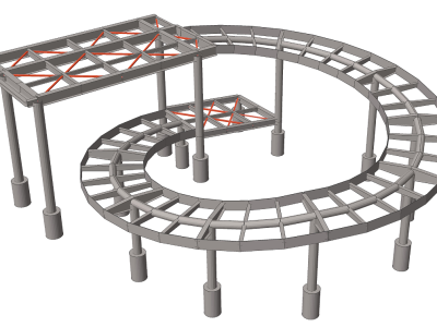
Circular Ramp
- Project Location
- Aichi Prefecture, JAPAN
- Applicable Standards
- Building Standards Act
- Building Scale
- Circular ramp with an outer diameter of 17.7m, inner diameter of 11.7m, and a height of 6.35m.
- Intended Use
- Ramp connecting to a pedestrian deck.
- Design Load
- Treated as a structure under the Building Standards Act and set seismic forces accordingly.
- Structural System
- Steel frame construction
• XY Direction: Moment resisting frame - Software & Tools
- MIDAS IT / MIDAS iGen
Key Design Considerations
• The columns and the beams connecting the columns in the circumferential direction are made of circular steel pipes. Whereas beams forming the slope floor are designed using H-shaped steel and CT steel.• As the structure is treated under the Building Standards Act, seismic forces were calculated with base shear coefficient of Co = 0.5, and a stress design was conducted using the allowable stress method.
• Arbitrary shape analysis software was used to create a model closely resembling the actual structure, and stress analysis was performed on the design.
• The slope floor consists of a concrete deck for durability and load-bearing capacity.