PROJECT PORTFOLIO

Seismic Evaluation
Seismic evaluation is a specialized service that assesses the earthquake resistance of existing buildings and provides tailored reinforcement solutions. Our approach begins with a thorough investigation of each building’s structural system, materials, and current condition. Using advanced analytical techniques, we evaluate structural safety during seismic events and determine the necessity for retrofitting. Based on the results, we develop practical and effective reinforcement plans aligned with the latest international standards and technologies. Our goal is to improve seismic resilience, safeguard building occupants, extend structural lifespan, and help maintain asset value.
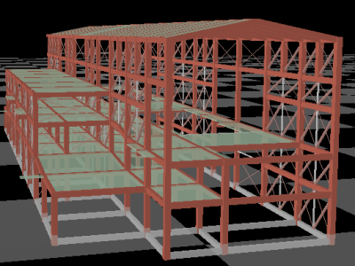
Turbine Building (Seismic Diagnosis and Reinforcement Design)
- Project Location
- Ibakaraki Prefecture, JAPAN
- Applicable Standards
- Seismic Diagnosis Criteria
- Building Scale
- Floor area: 28.0m × 81.5m, Height: 22.7m, Three stories above ground.
- Intended Use
- Turbine building
- Design Load
- The distribution of external forces during earthquakes was calculated based on the Ai distribution as per the Building Standards Act.
- Structural System
- • X-direction: Moment-resisting frame structure
• Y-direction: Braced structure - Software & Tools
- Union System / Super Build SS3
Key Design Considerations
• The structure comprises a steel frame system using H-section columns and a combination of H-section and truss beams. Column bases are root-wrapped column base, with reinforced concrete (RC) piles supporting the foundation.• A thorough on-site survey was carried out to verify the consistency between existing structural drawings and actual site conditions. This included checking member dimensions, connection details, and welding conditions to ensure reliable input for analysis.
• Seismic evaluation involved assessing the ultimate strength of critical components, including beam splices, joint connections, bracing systems, and column bases. For elements such as truss beams and specially arranged vertical braces, which are difficult to model directly, substitute cross-sections and equivalent stiffness values were used to approximate their behavior accurately.
• A drift angle of 1/50 was applied as the criterion for horizontal deformation capacity.
• During the retrofitting design phase, potential interference between proposed reinforcement members and existing structural elements was carefully reviewed on-site. Based on this assessment, practical and effective reinforcement methods were selected, including the installation of additional members, strengthening or replacing existing members, and reinforcing root-wrapped column base to improve seismic resilience
without compromising constructability.
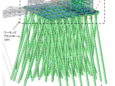
Seismic Evaluation of Loading Arm Structure
- Project Location
- Yamaguchi Prefecture, JAPAN
- Applicable Standards
- Seismic Design Criteria for High-Pressure Gas Facilities (KHK)
- Building Scale
- Floor area: 27.0m × 14.3m, Height: 27.2m, Three stories above ground, with a partial seven-story section.
- Intended Use
- Loading arm structure
- Design Load
- Calculated using the Level 2 alternative evaluation method.
- Structural System
- Upper Structure: Steel braced structure
Platform: Reinforced concrete structure (beam and slab system)
Foundation: Steel pipe piles - Software & Tools
- MIDAS IT / MIDAS iGen
Key Design Considerations
• The entire structure—from the steel pipe piles through the reinforced concrete platform to the upper steel braced frame—was modeled as a unified system to accurately reflect real-world behavior.• Seismic performance was assessed using response spectrum analysis in accordance with Level 2 seismic motion criteria.
• A comprehensive evaluation was carried out not only for the superstructure but also for critical components such as joints, base plates, anchor bolts, the RC platform, and foundation piles.
• Where structural deficiencies were identified in the existing facility, appropriate reinforcement plans were developed to restore and improve seismic performance.
• As the pile heads are located underwater, they were analyzed and designed as cantilever elements to account for unsupported length and lateral loading conditions.
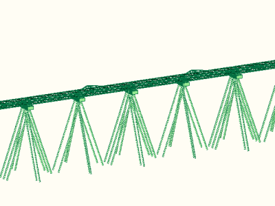
Piping Bridge (Seismic Diagnosis and Reinforcement Design)
- Project Location
- Yamaguchi Prefecture, JAPAN
- Applicable Standards
- Seismic Design Criteria for High-Pressure Gas Facilities
- Building Scale
- Short span: 6m / Long span: (Total length) 313m / Total of 9 units, with an average length of 34.8m per unit.
- Intended Use
- Pipe bridge for industrial plant infrastructure
- Design Load
- Level 2 seismic motion based on the Seismic Design Standards for High-Pressure Gas Facilities
- Structural System
- Short Direction: Moment-resisting frame
Long Direction: Braced structure (truss system) - Software & Tools
- Midas iGen
Key Design Considerations
• Seismic diagnosis and retrofit design were conducted for an existing pipe bridge to meet updated seismic performance requirements.• Response spectrum analysis was carried out under Level 2 seismic motion conditions, utilizing the alternative evaluation method for enhanced assessment accuracy.
• The entire structural system—including pile foundations—was modeled to capture the coupled dynamic response between the superstructure and substructure.
• Retrofit planning was informed by detailed on-site investigations, with a focus on practical constructability and minimizing interference with ongoing plant operations.
• Reinforcement strategies were proposed based on both structural performance needs and site-specific constraints, ensuring feasible and effective seismic upgrades.