PROJECT PORTFOLIO
Plant Design
Plant Design Project List
Plant design involves the engineering of industrial facilities across sectors such as chemical, petroleum, energy, and food production. At RISE, we develop structural plans that emphasize safety, durability, cost-efficiency, and ease of maintenance—ensuring environments optimized for stable, high-performance production. By integrating the latest technologies and staying aligned with regulatory standards, we deliver sustainable plant designs that enhance business productivity while minimizing environmental impact.
Design of Tsunami Protection Wall
- Project Location
- Kagoshima Prefecture, JAPAN
- Applicable Standards
- Building Standards Law
- Building Scale
- Floor area: 65.5m × 22.3m / Height: 15.0m
- Intended Use
- Tsunami Protection Wall
- Design Load
- Hydrostatic Pressure from Tsunami, Wave Height: 15.0m
Spectral Analysis during Earthquakes
Consideration of Falling Debris from Tornadoes - Structural System
- Steel Framing
Short Span Direction: Braced Structure
Long Span Direction: Frame Structure - Software & Tools
- MIDAS IT / MIDAS iGen
Key Design Considerations
• Tsunami Hydrostatic Pressure:Hydrostatic pressure was calculated based on the reference elevation of EL+4.5 m. While the estimated tsunami wave height was EL+8.0 m, a design height of EL+15.0 m was adopted to account for a safety factor—corresponding to three times the pressure derived from the estimated wave height. Furthermore, for elevations above EL+12.0 m, an additional pressure equivalent to a 3.0 m water height was included. This approach ensures robustness in the analysis under extreme conditions. Both push wave and pull wave scenarios were considered.
• Seismic Spectral Analysis:
Eigenvalue analysis was conducted up to 300 modes. For each direction (X, Y, Z), the mode with the highest effective mass ratio was selected. The natural period corresponding to the maximum response factor was used: 16th mode (X-direction), 1st mode (Y-direction), and 202nd mode (Z-direction).
• Debris from Tornadoes:
A reinforced net was installed above the platform to absorb impact from falling debris. Only the load distributed to each column was considered in the structural design.
• Column Footing Shear Resistance:
Significant shear forces were anticipated at column bases. Shear keys were installed beneath the base plates to resist horizontal forces effectively.
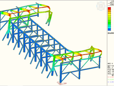
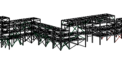
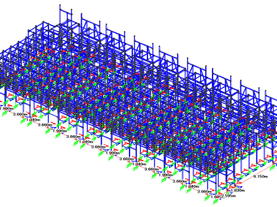
Piping Rack (Seismic Diagnosis and Reinforcement Design)
- Project Location
- Ibaraki Prefecture, JAPAN
- Applicable Standards
- Building Standards Act, Fire Service Act
- Building Scale
- Approximately 200m x 4.0m in plan, with a height of 14.0m
- Intended Use
- Piping Rack
- Design Load
- Seismic force settings were made in accordance with the Building Standards Act and the Fire Service Act.
- Structural System
- XY Direction: Frame + Bracing Structure
- Software & Tools
- MIDAS IT / MIDAS iGen
Key Design Considerations
• Conducted an on-site survey to verify consistency between the existing drawings and actual conditions. This included checking member joints and weld conditions at splice locations.• Built an analysis model of the upper structure using arbitrary shape analysis software to perform stress analysis. The foundation was modeled separately for sectional capacity evaluation.
• Independently evaluated the strength of special structural members and conducted a detailed review.
• Applied allowable stress design principles in structural evaluation.
• Verified potential interferences of reinforcement members on-site and developed a reinforcement plan accordingly.
Cable Rack
- Project Location
- JAPAN
- Applicable Standards
- Building Standards Act
- Building Scale
- Plan dimensions: 49.0m x 20.1m, height: 8.7m
- Intended Use
- Cable Racks within a Data Center
- Design Load
- • The design seismic intensity was determined by considering both the building’s seismic acceleration and the rack’s dynamic response.
• The negative pressure acting on partition walls during adjacent rack construction was also considered. - Structural System
- XY Direction: Bracing Structure
Column Base: Mechanical Post-Installation Anchor - Software & Tools
- Bentley /STAAD Pro.
Key Design Considerations
• When introducing an overseas-manufactured cable rack system in Japan, it was necessary to increase the size of certain components and add bracing reinforcement due to differing seismic design standards.• The installation of bracing was limited in areas beneath the racks where cables and servers are located, to maintain accessibility and avoid interference.
• As the system rack product had limited design flexibility, coordination with the client and manufacturer was required on a case-by-case basis.
• After clarifying the manufacturer’s allowable scope of modifications, the design team worked to ensure feasibility within those constraints.
• While a seismic response twice the building’s acceleration is sometimes used as a conservative safety factor in facility design, we calculated a more realistic response based on the rack’s natural frequency and applied a practical design seismic intensity.
• The column base was designed as a semi-fixed spring-supported base using anchor bolts.
Stiffness was considered in place of simple pinned connections. Due to the asymmetrical arrangement of bolts, different spring constants were applied in the X and Z directions.
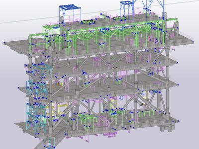
Floating LNG Plant Structure (Module)
- Project Location
- Offshore (Onboard a Ship)
- Applicable Standards
- AISC, etc
- Building Scale
- Main Structure Dimensions: Plan 15.3m x 42.5m, Height 27.0m (3 stories)
- Intended Use
- Support Structure (Module) for Equipment and Piping
- Design Load
- Inertial Force due to Sea Surface Acceleration
- Structural System
- XY Direction: Frame + Bracing Structure
- Software & Tools
- STAAD Pro.
Key Design Considerations
• This structure is a plant module installed offshore, mounted on a ship.• Due to the large inertial forces from sea surface acceleration, the entire main structure is composed of assembled members.
• To avoid directional weaknesses in vertical elements, steel pipe sections were used for columns and vertical bracing.
• The structural design for the main part was completed in advance to accommodate the production schedule of assembled members.
• Since the modules are assembled on land and later lifted onto the vessel, structural considerations were also made for crane installation during lifting operations.
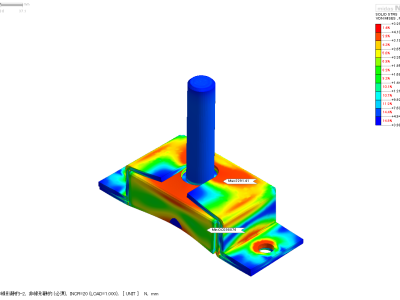
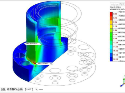
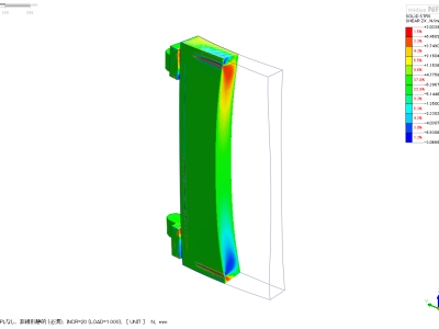
Design of Hinges for Ultra-Large Watertight Doors
- Project Location
- JAPAN
- Applicable Standards
- Electricity Business Act, Atomic Energy Basic Act
- Intended Use
- Watertight Doors within a Nuclear Power Plant
- Pressure resistance performance
- A structure capable of withstanding water pressure of 9.0 t/m².
- Seismic Performance
- A structure capable of withstanding horizontal seismic intensity of 1.0G and vertical seismic intensity of 0.8G during both opening and closing operations.
- Materials Used
- Stainless steel materials (SUSF304, SUS304N2, SUS403, SUS304)
- Software & Tools
- MIDAS IT /midas FNX (FEM Analysis Program)
Key Design Considerations
• A 3D model was created for all components, with contact conditions defined at each interface.• The external force was simulated by modeling a 60-ton door and applying seismic inertial forces based on its self-weight in the analysis.
• Stress levels were evaluated under both long-term and seismic conditions, confirming compliance with allowable stress limits.
• Deformation levels were also assessed in all cases and confirmed to be within allowable displacement limits.
Blast Wind Resistance Evaluation of Underground Shelter Doors
- Project Location
- JAPAN
- Intended Use
- Underground Disaster Shelter
- Pressure resistance performance
- A structure capable of withstanding a pressure of 400 kN/m²
- Materials Used
- Reinforced concrete structure with steel plate covers around the perimeter
- Software & Tools
- MIDAS IT / midas FNX (FEM Analysis Program)
Key Design Considerations
• Verification that the structure has sufficient strength to resist a blast load of 400 kN/m²• Modeled reinforced concrete as an isotropic material in the FEM analysis. Structural strength was evaluated separately based on the resulting stress distribution.
Evaluation of Seismic Brackets for High-Rise Racks
- Project Location
- JAPAN
- Intended Use
- Seismic brackets for preventing rack overturning
- Software & Tools
- MIDAS IT/midas FNX (FEM Analysis Program)
Key Design Considerations
• Evaluated whether the seismic bracket could withstand upward tensile forces generated during earthquakes.• Analyzed the contact behavior between the rack leg and the two-piece bracket assembly to ensure proper load transfer and performance.