PROJECT PORTFOLIO

Piping Design
Our piping design services focus on route planning and stress analysis to ensure safe and efficient piping systems. We develop optimal piping layouts that minimize interference with equipment and structures. Stress analysis includes evaluating loads from temperature changes and internal pressure, as well as assessing resistance to seismic activity and vibrations. This ensures the strength and durability of the entire system. Our designs comply with the latest regulations and safety standards, while also prioritizing constructability and ease of maintenance.
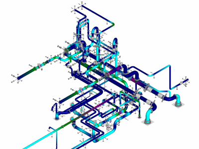
Seismic and Thermal Stress Analysis of Plant Piping
- Project Location
- JAPAN
- Applicable Standards
- High Pressure Gas Safety Act, ASME B31.3
- Intended Use
- Manufacturing Plant
- Design Load
- Dead Load, Thermal Load, and Seismic Load
- Software & Tools
- Bentley / AutoPIPE AutoPIPE Nozzle
Key Design Considerations
• Performed seismic performance evaluation and thermal stress analysis for plant piping within a factory.• Expansion joints were introduced to accommodate phase differences between building-mounted supports and internal equipment platforms.
• Piping stress analysis included evaluation of stresses caused by dead load, thermal stress, seismic inertial forces, and displacement responses.
• Additional support structures were introduced due to the high seismic demands.
• Equipment nozzles were evaluated using AutoPIPE Nozzle.
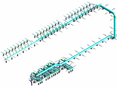
Seismic and Thermal Stress Analysis of HVAC Piping
- Project Location
- JAPAN
- Applicable Standards
- ASME B31.3 compliant
- Intended Use
- Factory
- Design Load
- Dead load, Thermal load, and Seismic load
- Software & Tools
- Bentley / AutoPIPE
Key Design Considerations
• Performed seismic performance evaluation and thermal stress analysis for air conditioning piping installed in the factory.• Calculated response displacements based on the inter-story drift angle of the building structure.
• Pipe stress analysis included evaluation of stresses due to self-weight, thermal expansion, seismic inertial forces, and displacement responses.
• Support configurations were optimized to distribute loads from building-side supports.
• Equipment nozzle evaluation was omitted due to the presence of nearby expansion joints.
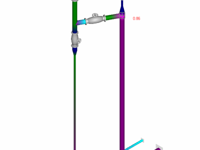
Seismic Performance Evaluation of Bottom Piping for Spherical Tanks
- Project Location
- JAPAN
- Applicable Standards
- High Pressure Gas Safety Act (KHKS 0861)
- Intended Use
- Refinery
- Design Load
- Dead load and seismic loads
- Software & Tools
- Bentley / AutoPIPE, AutoPIPE Nozzle
Key Design Considerations
• Performed seismic performance evaluation of spherical tank bottom piping at the refinery using the Level 1 Modified Seismic Design Method and Level 2 Alternative Evaluation Method.• For above-ground supports, seismic response displacement was considered only at the tank nozzle section, as ground improvement had already been completed.
• Pipe stress analysis was carried out in accordance with the High-Pressure Gas Safety Act (KHKS 0861), focusing on stresses caused by seismic inertial forces and displacement responses.
• Equipment nozzles were evaluated using AutoPIPE Nozzle.
• Conducted strength assessment of flange connections.


